
Thursday, 21 June 2012
Wednesday, 20 June 2012


FINAL 3D Printed Model/File

This is the final iteration file that was sent off to be 3D printed. Unfortunately I was unable to obtain a professional copy of NetFab and so not all errors were able to be fixed (indicated by red). Fortunately though, the 3D printing place I am sending the .STL file to will be able to fix the rest for me.
Rejected Shapeways Models
These are some of the errors that occurred when trying to send my file to shape ways

Error 1: The material that I had picked for 3D printing had a minimum thickness of 0.8mm, however as seen here, their model checking program has found that the model I sent had a large number of areas where the thickness was 0.48mm's. This error was easily and rapidly (took a minute) rectified however thanks to the parametric nature of these models.

Error 2: This error was generated as the new model I sent in had faces that were seen as 'reversed'. When a 3D printer undertakes a print, it analyses a model and checks what surfaces are exterior surfaces and which are internal surfaces. For this error, it is highlighted that there are some internal defined faces facing outside.
To rectify this error I downloaded two programs called MeshLab and NetFab. MeshLab allows for the conversion of a number of different 3D model formats into the industry standard .STL file format. This file format was then sent to NetFab, a 3D model checker that automatically runs tests and fixes them in preparation for 3D printing and rapid prototyping.

MeshLab

NetFab
Grasshopper Definition!
Download link for the GH definition used for Assignment 3 (final iteration model)
https://rapidshare.com/files/1635441161/New_Helix_Iteration13__autosave__autosave_.gh
https://rapidshare.com/files/1635441161/New_Helix_Iteration13__autosave__autosave_.gh
Tuesday, 5 June 2012
Grasshopper Hyperbolic Tower Definition

Download Link:
https://rapidshare.com/files/2458607134/GH_TOTAL.jpg
Wednesday, 30 May 2012
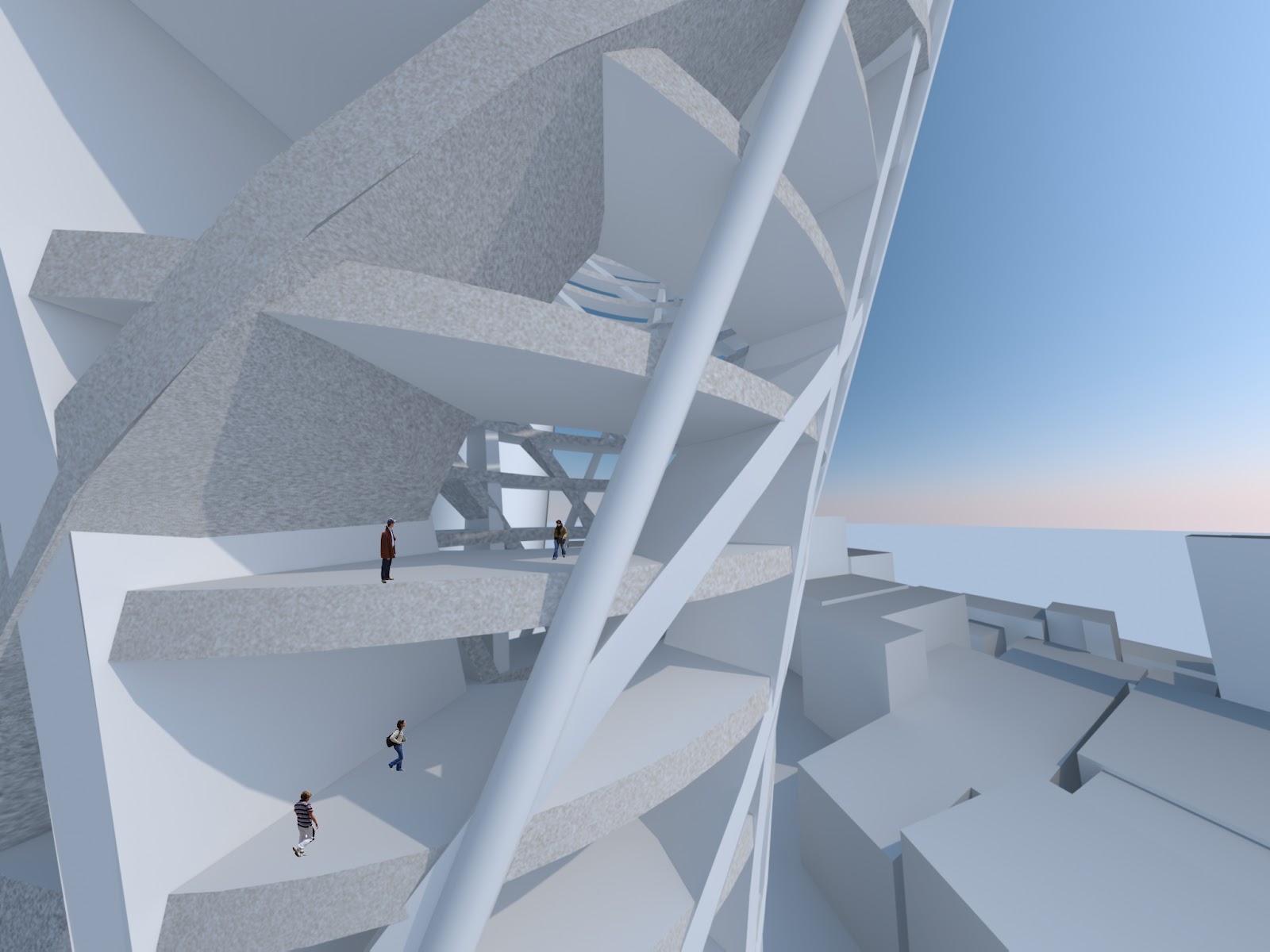
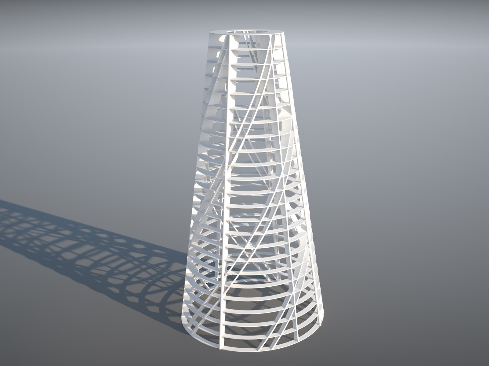
Current Model
I've finally created a final design in grasshopper. The geometry itself is a vertical tower consisting of many different circular rings along the vertical axis which serve as floor plates. These floor plates are then connected together by four columns that follow the curve and height of the tower. A series of pipes arranged in an X also follow the curvature of the tower while a hyperbolic helical geometry runs the vertical length of the tower. The amalgamation of these four geometries create the bulk of the whole tower.
Floor Plates


Vertical Columns


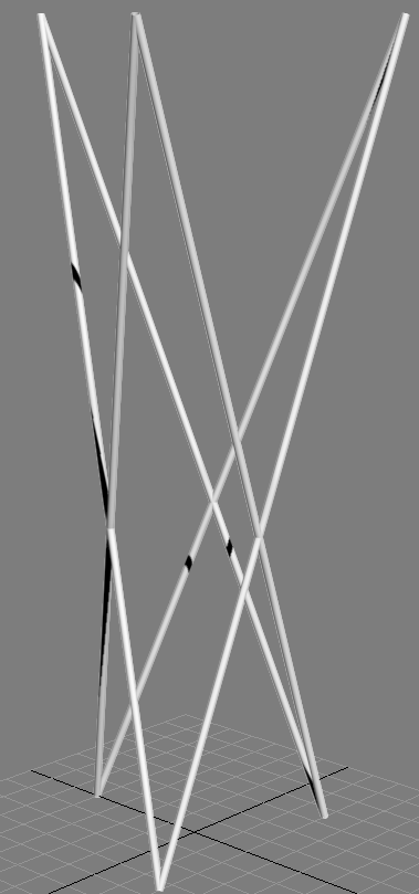
Vertical Pipes

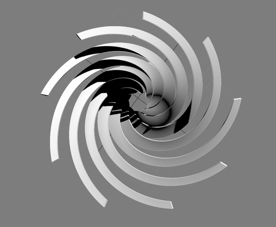
Hyperbolic Helix


Combined Geometry


Subscribe to:
Comments (Atom)